What is a Motherboard?
Motherboard
is the most important component in any personal computer. It contains almost
every important elements of the computer. Sometimes instead of the calling it
“motherboard”, IBM refers to is as “system Board” or “ Planner Board” , some
other manufacturer refer to this as the “Logic Board”.
The
motherboard is
the main circuit board inside
the PC which
holds the processor,
memory and expansion slots and
connects directly or indirectly to every part of the PC. It’s made up of a
chipset(known as the “glue logic”), some code in ROM and the various interconnections or buses.
The
original PC had a minimum of integrated devices, just ports for a keyboard and
a cassette deck (for storage). Everything else, including a display adapter and
floppy or hard disk controllers, were add-in components, connected via expansion
slots.
Over
time, more devices have been integrated into the motherboard. It’s a slow trend
though, as I/O ports and disk controllers were often mounted on expansion cards
as recently as 1995. Other components - typically graphics, networking, SCSI
and sound - usually remain separate. Many manufacturers have experimented with
different levels of integration, building in some or even all of these
components. However, there are drawbacks. It’s harder to upgrade the specification
if integrated components can’t be removed, and highly integrated motherboards
often require non-standard cases. Furthermore, replacing a single faulty
component may mean buying an entire new motherboard. Consequently, those parts
of the system whose specification changes fastest -
RAM,
CPU and graphics - tend to remain in sockets or slots for easy replacement.
Similarly, parts that not all users need, such as networking or SCSI, are usually
left out of the base specification to keep costs down. The basic changes in
motherboard form factors over the years are covered later in this section - the
diagrams below provide a detailed look at the various components on two
motherboards. The first a Baby AT design, sporting the ubiquitous
Socket
7 processor connector, circa 1995. The second is an ATX design, with a Pentium
II Slot 1 type processor connector, typical of motherboards on the market in
late 1998.

A
conventional motherboard comprises of various components such as:
1)
Card slots
2)
Power connectors
3)
IDE connectors
4)
SATA connectors
5)
Socket
6)
CMOS
7)
BIOS
8)
Coprocessor
9)
RAM slots
Card
slots:
These
are also called expansion slots. The expansion slots are long thin connectors
on the motherboard, near the backside of the computer. Various expansion cards
are connected to the motherboards through data, address and control lines/buses
on these slots.
One can connect various expansion cards such
as display card, hard drive controller, sound card, network card, modem card
etc. on these slots. When an adapter card is connected to the expansion slot,
it is actually connected to the data, address and control bus on the
motherboard.
These
card slots are of different types based on their speeds. They are:
1)
8 bit
2)
16 bit
3)
32 bits
4)
64 bits
you
might be wondering what exactly does this bits thing mean. It is explained
below. A bus is an electronic path on which signals are sent from one part of the computer to
another.
These
buses are categorizes according to the number of BINARY DIGITS (bits) that they
can transfer at a time.
If
the data bus is 8 bit wide then it can transfer 8 bits of information at a time
and called an 8 bit bus.
On
a 8 bit data bus transferring 16 bit data requires two data transfers Another
very common term while talking about bus is , its “ bandwidth”. The bandwidth of a bus is the measure of data that can fit
in the bus at a given time.
You
can increase the data movement through a bus either by increasing the bus
width( from 8 bit to 16 bit) of by increasing the bus bandwidth (8 Mhz to 20
Mhz).
This
is similar to the way you can increase water output from a pipe, either you can
increase the pipe diameter or you can increase the water flow.
Data
Bus : Is a set of wires or tracks on the motherboard. Data bus is used to
transfer data from one part of the computer to another part.
Address
Bus : is a set of wires or tracks on the motherboard Printed Circuit Board(PCB)
which is used to specify address of a memory location
Depending
on the width and the technology, the expansion slot bus can be
divided
into the categories mentioned above.

32-bit card slots

The big long slots are the 8-bit card slots

These are the 16 bit card slots
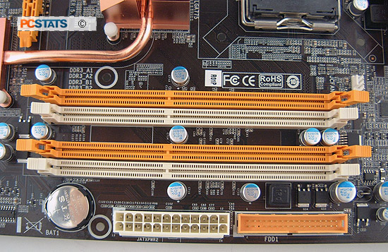
Power
connector:
The
motherboard requires electrical energy to pass signals across the bus line to
different parts of motherboard. The power comes from the SMPS after filtering
the 230 volts of power supply. There are two types of power supplies they are
AT and ATX.
AT
power supply:
This
AT is called Advanced Technology. This gives 12 pins to supply electricity to
the mother board. This is used in the old motherboards like in p1, p2, p3
motherboards
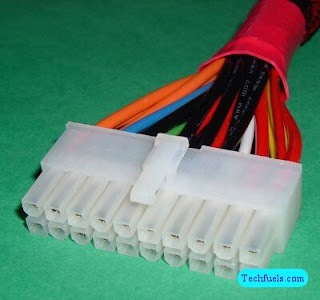
ATX
power supply:
This
ATX is called advanced technology extended. These power connectors are in three
different levels. The first level have 20 pins and are found in latest
generation of p3 motherboards and first generation of p4 motherboards. The
second level have 24 pins and is found in p4 motherboards. The third level
consists of 28 pins and this is present in second and third generations of p4
motherboards.

This is the 20 pins power connector


IDE
connectors:
These
are the ports where we connect the IDE hard disk drives and floppy disk drives
to the motherboards. In the p1, p2, p3 and the beginning of p4 motherboards we
have 2 IDE connectors but as there is development in technology and SATA
connectors are introduced the function of IDE hard disk has been reduced and
motherboards are manufactured with only one IDE connectors and more SATA
connectors and floppy drive connectors are being ignored completely.

SATA
connectors:
These
are the latest technology connectors introduced after the IDE connecters
replacing them in these connectors we do not need a jumper section as we can
connect only one hard disk to a connector at a time.

Socket:
This
is the place where we add processor in the motherboard. A CPU socket or CPU slot is a mechanical component that
provides mechanical and electrical connections between a microprocessor and a
printed circuit board (PCB). This allows the CPU to be replaced without
soldering.To learn more about socket please refer processor.

This is the new socket which is in use now a days

This is the old socket and this is not in use nowadays
CMOS:
This
is complementary metal oxide semiconductor. In old IBM XT or compatible system,
BIOS, with the help of jumpers, detected what all components are connected to
the computer system.
IBM
AT and higher systems do not contain these jumper switches and instead use a
CMOS memory to store the system configuration, date, and time etc. information.
This CMOS memory receives power from a battery accompanying it, this battery
helps it retains the information stored in it even when the system is switched
off. When an AT or higher system is switched on, BIOS matches the information
stored inside the CMOS with the components connected to the system and if it
finds some mismatch or error, the BIOS displays some error message, explaining
the problem.

BIOS:
BIOS
is an abbreviation if Basic Input Output System. It is one of the most
important program stored in the ROM. BIOS program lets your application program
and the hardware such as floppy disk, hard disk, video adapter etc. communicate
with each other. It is pronounced “bye-os”. The BIOS also contains a program
called Power-On-Self-Test or POST. This post program checks the motherboard and
other devices connected to the computer during the system power-on time. IBM
made the original BIOS for their copyright product, but many compatible BIOS
program BIOS program are available from Award, Phoenix, American Megatrends
Inc. (AMI) etc. various manufacturers.

Coprocessor:
Coprocessor
is a special purpose microprocessor, which is used to speed up main processor
job by taking over some of the main processors work. Most common type of
coprocessor is a math coprocessor. Coprocessor chips are used to help the main
processor in carrying out its
various
functions.
A
math coprocessor helps main processor in performing mathematical calculations
Older system (XT, AT, AT-386) required a
coprocessor chips to be inserted into special socket on the motherboard, but
the current federation of CPU’s have math coprocessor built inside the main processor
itself.
RAM
slots:
This
is the place where we add RAM in the motherboard. Depending upon the type of
RAM the RAM slots keep changing. To find which ram is used in a particular
generation please go to the page related to RAM.
There
are 4 types of RAMs and their slots:
The
images are given below:


This is the EDO RAM slot this is different from other
types of RAM slot. we must insert the RAM at an
angle and straighten it to fit it in the slot.
This is a SD RAM slot we can observe some notches
in it

This is a DDR-1 RAM slot

This is a DDR-3 RAM slot
Nice and quite informative post. I really look forward to your other posts.
ReplyDeleteLenovo - 14" ThinkPad Notebook - 4 GB Memory - 320 GB Hard Drive - Black
Lenovo - Refurbished - 15.6" ThinkPad Edge Notebook - 4 GB Memory - 500 GB Hard Drive
Computer Hardware: Motherboard >>>>> Download Now
ReplyDelete>>>>> Download Full
Computer Hardware: Motherboard >>>>> Download LINK
>>>>> Download Now
Computer Hardware: Motherboard >>>>> Download Full
>>>>> Download LINK eh