What is a Horn Antenna?
What is a Horn Antenna?
Horn antennas are used mainly for UHF and microwave frequencies. It consists of a flaring metal wave guide shaped like a horn, to direct radio waves in a beam. They can also be used as feed antennas or feed horns for larger antennas like parabolic reflector antennas. A low cost 21 cm horn antenna radio telescope for education and outreach has been described by Harvard University. That has an aperture of 75 cm along the H-plane and 59 cm along the E-plane, with a gain of 20 dB. E-plane is the direction of the electric or E-field while H-plane is the direction of the magnetic or H-field in the waveguide.
They mention that it can be built entirely by students using simple components. Low noise amplifiers, band-pass filters and a software defined radio USB receiver provided digitized samples for spectral processing in a computer. A pyramidal horn was used way back in 1951 at Harvard University to detect the 21cm hydrogen line from Milky Way galaxy.
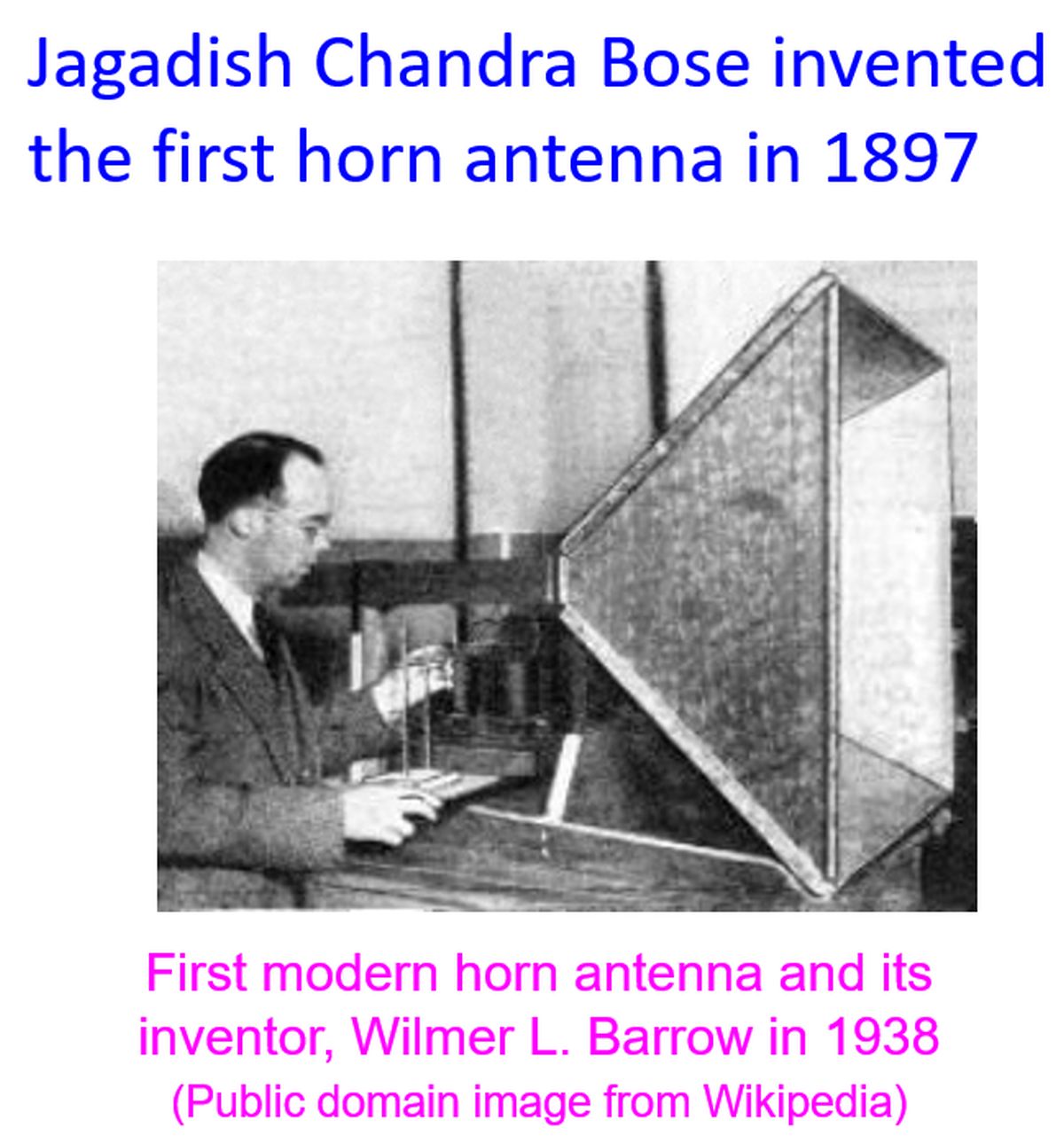
Jagadish Chandra Bose invented the first horn antenna in 1897 for his pioneering experiments with microwaves. Wilmer Barrow and GC Southwort invented the modern horn antenna independently in 1938. Advantages mentioned for horn antenna are moderate directivity, broad bandwidth, low losses, simple construction and adjustment. As the horn antenna has no resonant elements, they can operate over a wide range of frequencies, providing a wide bandwidth. Some of them may operate from 1 GHz to 20 GHz. Gain of horn antennas can be as high as 25 dBi.
Usual setup is a coaxial cable introducing the radio waves into a wave guide which takes it to the horn antenna. The central conductor of the coaxial cable would project into the waveguide to form a quarter wave monopole antenna. In outdoor implementations as in feedhorns of parabolic reflector antenna, the open mouth of the horn may be covered with a plastic sheet which is transparent to radio waves, to keep away rain water.
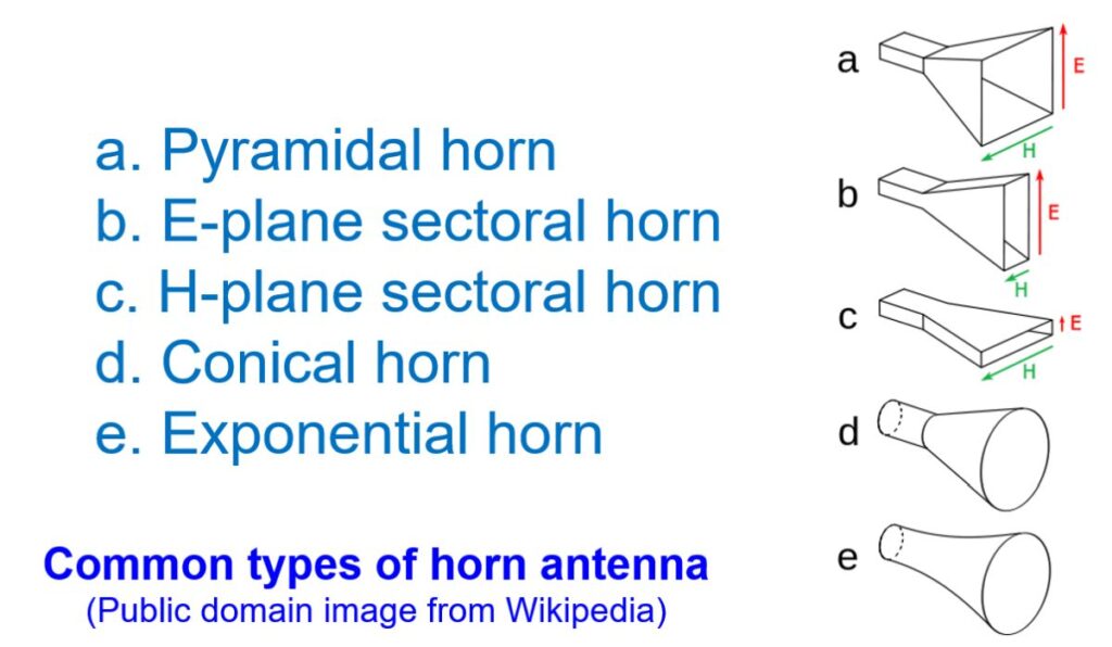
Horn antenna gives a gradual change in impedance from the waveguide to free space. Otherwise, a sudden change in impedance could lead to reflection of significant amount of wave energy back to the source through the wave guide, causing standing waves and overheating of the final stages. Minimum reflection of power can be obtained with an exponential taper of the horn shape. But they are more difficult to design and fabricate. So conical and pyramidal horns are more widely used. In applications like satellite antennas and radio telescopes where minimum signal losss is needed, exponential taper may be used.