
Use of 3D Printing for Horn Antenna Manufacturing


1
Department of Communication Technologies, Electronic Warfare and Radiolocation, University of Defence, 662 10 Brno, Czech Republic
2
Department of Radio Electronics, Brno University of Technology Brno, 662 10 Brno, Czech Republic
*
Author to whom correspondence should be addressed.
Electronics 2022, 11(10), 1539; https://doi.org/10.3390/electronics11101539
Submission received: 31 March 2022
/
Revised: 19 April 2022
/
Accepted: 9 May 2022
/
Published: 11 May 2022
(This article belongs to the Special Issue New Generation Design of Antennas)
Abstract
:This article describes the manufacturing of a horn antenna using a 3D commercial printer. The horn antenna was chosen for its simplicity and practical versatility. The standardised horn antenna is one of the most widely used antennas in microwave technology. A standardised horn antenna can be connected to standardised waveguides. The horn antenna has been selected so that this antenna can be fabricated by 3D printing and thus obtain the equivalent of a standardised horn antenna. This 3D horn antenna can then be excited by a standardised waveguide. The 3Dprinted horn antenna with metallic layers has very good impedance characteristics, standing wave ratio and radiation patterns that are close to those of a standardised horn antenna. The 3D-based horn antenna is suitable for applications where low antenna weight is required, such as aerospace and satellite technologies. The article also describes a manufacturing procedure for a horn antenna (E-sector horn antenna) that is plated with galvanic layers of silver and gold. The design of the plated horn antenna in the Matlab application using the Antenna Toolbox extension is also described, including 3D printing procedures, post-processing procedures (plating) and practical testing of its functionality. The measured results are compared to simulations of the standardised horn antenna and then analysed.
1. Introduction
The article introduces options for using 3D printing when manufacturing a horn antenna. Nowadays, there is great progress in 3D printing technologies, both in the 3D printers themselves and in the materials from which the final object is printed. Three-dimensional printing is the process of creating a three-dimensional fixed object from a digital file, where the resulting printed object is gradually created by laying (printing) continuous layers of material until the entire object is completed [1,2,3]. This technology is rapidly developing along with today’s demands of end users. There are many 3D printer manufacturers world-wide, who are interested in developing and manufacturing different kinds and sizes of 3D printers. Our proposed horn antenna was printed on an original Prusa i3 MK3S+ 3D printer from Prusa Research [4]. This printer has a print area of 25 × 21 × 21 cm with the option to adjust the print quality (print height) between 0.05 and 0.35 mm.
A standard E-sector horn antenna was selected to be 3D printed so that the parameters of the manufactured and standardised antenna could be accurately compared. In order to be able to print the antenna on a 3D printer, it was necessary to model (design) parts of the antenna in a program designed for 3D modelling. Nowadays, many software programs are available for drawing 3D objects. Autodesk Inventor Software and Onshape’s programming environment were selected for the modelling of our horn antenna. Exact geometric parameters of a standardised horn antenna were measured and modelled in both Autodesk Inventor (paid license) and Onshape (freeware).
Autodesk Inventor is a parametric, adaptive 3D program—a software CAD application from Autodesk [5,6]. Figure 1a shows a modelled horn antenna in Autodesk Inventor. Onshape is a computer design software system supplied over the internet through the model “Software as a Service” [7]. Figure 1b shows a modelled horn antenna in Onshape. After printing the antennas on a 3D printer, both antennas had the same geometric parameters as the standardised horn antenna. Both programs are, therefore, suitable for our application. Onshape has the advantage that it is not difficult to install, as it works online.
2. Analysis of a Standard Horn Antenna
When choosing the horn antenna itself, it was important to choose a type of horn antenna that could easily be printed on a 3D printer and could be galvanically plated. The E-sector horn type (see Figure 2) was selected. This was very important for comparing (evaluating) simulations with the measured data of the manufactured horn antenna [8].
2.1. Description of a Standardised Horn Antenna
A sector horn antenna (see Figure 3) is a special horn antenna extending only in one plane. These horn antennas are also referred to as planar or flat. The estuary of this horn antenna type may, in some cases, be considered a one-dimensional mouth [9,10,11].
Radiation characteristics of sector horn antennas have the shape of a fan, which is narrow in one plane and wide in the other plane. Typical use of this radiation pattern is in radiolocation technology. If the horn is open in plane H (magnetic field lines of force), then there is a significant decrease in the lateral lobe level and a decrease in the beam width of the radiation pattern, compared to the direction of the opening only in plane E (electric field lines of force). A composition of the sector horn radiation pattern open in both E and H planes produces radiation patterns typical of pyramidal horn antennas [10,11,12,13].
2.2. Features of a Standardised Horn Antenna
For simulations of horn antennas with different metal plating, it is important to first perform a detailed analysis of the standardised E-sector horn antenna (see Figure 4). This analysis includes detailed measurements of the horn antenna radiation properties and the precise measurement of the actual standardised horn antenna dimensions. This information was very important for both the simulations in the Matlab environment and for the actual 3D printing of the horn antenna.
Figure 4 and Table 1 show the exact dimensions of the E-sector horn antenna. According to the transversal dimensions of the excitation waveguide of this antenna, the working band frequency was determined as 8.2–12.4 GHz (see Figure 5), where TE10 is the dominant mode. The limit frequency fm of the TE10 mode was, for this waveguide, equal to 9.55 GHz [14,15,16,17,18].
A Matlab simulation program with the Antenna Toolbox was selected to simulate the pattern of the proposed galvanically plated antenna. Figure 6 shows the gold-plated horn antenna designed in the Matlab Antenna Toolbox environment. Figure 7 and Figure 8 show directional characteristics of the proposed horn antenna. All the simulations were performed at a frequency of 9.5 GHz.
3. Manufacturing of a Horn Antenna
3.1. Material Selection (Filament) for Horn Antenna
Before printing a horn antenna on a 3D printer, it is important to choose the most suitable filament (printing string). The most commercially available and most used filaments (PLA, ABS and PET/PET-G) were used for comparison [19].
3.1.1. PLA Material
PLA material (polylactic acid) is the most used material for 3D printing, and at the same time is the most versatile material for the FDM method. PLA is biodegradable, as it is made from potato or corn starch. Due to its low thermal expansion, it is suitable for printing large products that do not twist. PLA prints are flexible, hard and durable.
3.1.2. ABS Material
ABS material (acrolonitril–butane–styrene) is a tough, rigid and solid material made from oil. It is biodegradable and has a very high thermal expansion. This causes complications when printing large products as the product twists and peels off the printing pad. Therefore, the printer must be equipped with a heated pad and the material must be slowly cooled during printing.
3.1.3. PET/PET-G Material
PET/PET-G (polyethylene-terephthalate) is the most used plastic in the world, the advantage of which is the possibility of recycling. Its modified PET-G version is less fragile and more impact-resistant. PET-G combines the properties of ABS and PLA materials and is suitable for printing mechanically stressed parts [20]. A general comparison of the above-described types of materials (filaments) is shown in Table 2.
ABS material was selected from the above options for our application [21]. Although ABS is more demanding to print, it is most suitable for galvanic plating. When applying galvanic plating, the printed antenna is exposed to temperatures of around 70 °C. PLA, PET and PET-G materials would become deformed during this process. For 3D printing, the “Prusament black EasyABS” material was selected, which is a printing string (filament) of 1 kg with a diameter of 1.75 mm.
3.2. Preparing Antenna Design for the 3D Printing
When designing the horn antenna using Autodesk Inventor software and Onshape’s program environment, the design files must be exported to an STL format as they are saved. STL files describe only the surface geometry of a three-dimensional object without representing the colours, textures, or other common CAD attributes of the model [22,23,24].
Different types of slicers work with these other files. This is a software that edits CAD data for 3D printing. These files then have the GCODE extension. The GCODE file contains commands in G-code, which stands for geometric code. This is a programming language whose main task is to instruct the 3D printer on how to move the printer in three dimensions, how quickly to print and instructions for setting the temperature. GCODE files are created by “slicing” programs. Simplify3D, PrusaSlicer and Slic3r are among the best-known programs that can convert 3D objects into G-code.
These programs convert CAD drawings into G-code, which a 3D printer is able to read. PrusaSlicer was selected for our application, and it is a free software available on PrusaSlicer a.s website, the Czech 3D printer manufacturer [25]. Figure 9 shows a horn antenna in PrusaSlicer.
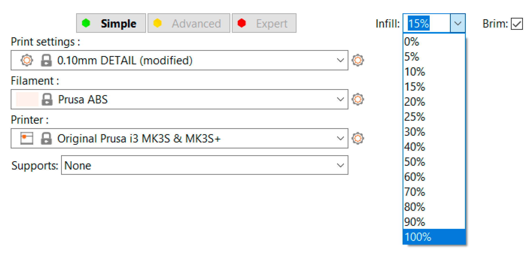
Print quality was set to 0.1 mm (height of one layer). For the actual 3D printing, a so-called “collar” was used to prevent twisting and peeling off the printing pad. Print settings are displayed in Figure 10.
3.3. Preparing Printed Antenna for Galvanic Plating
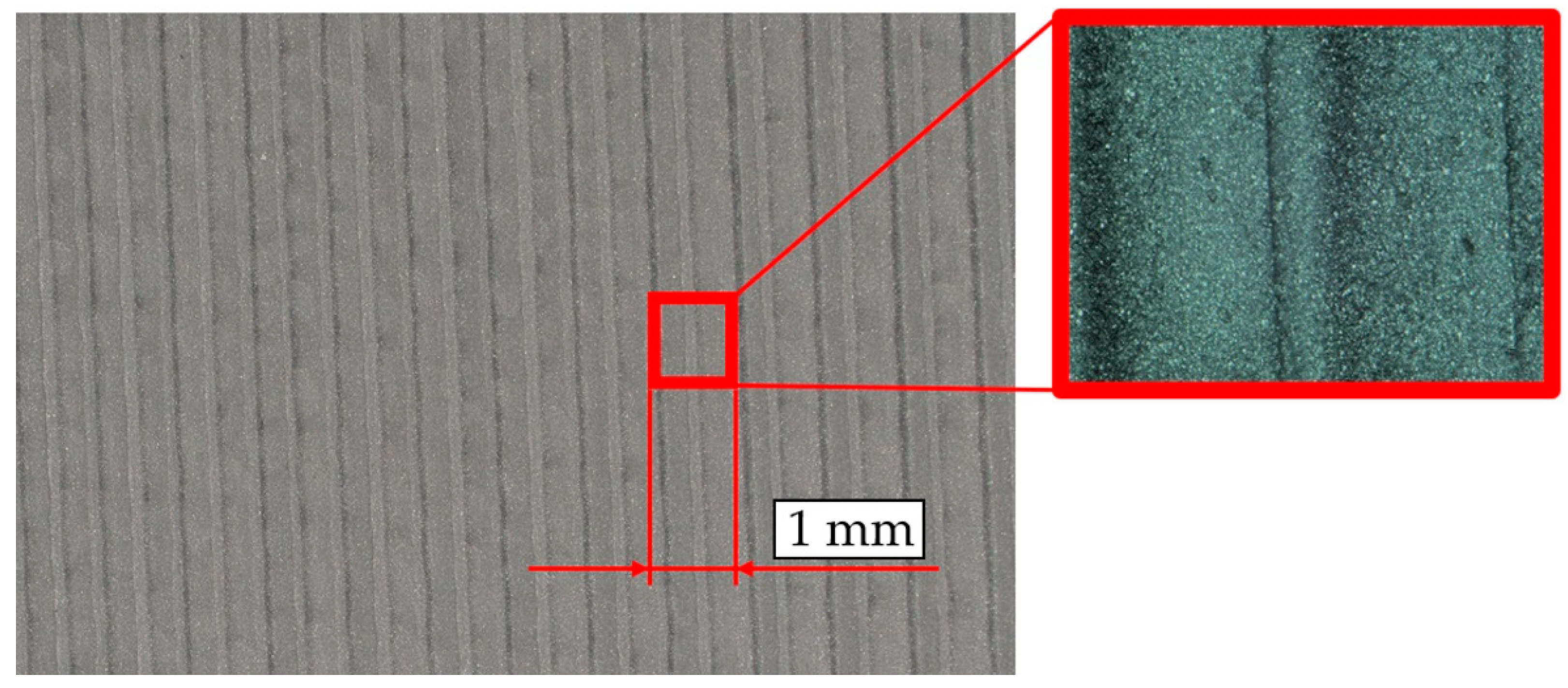
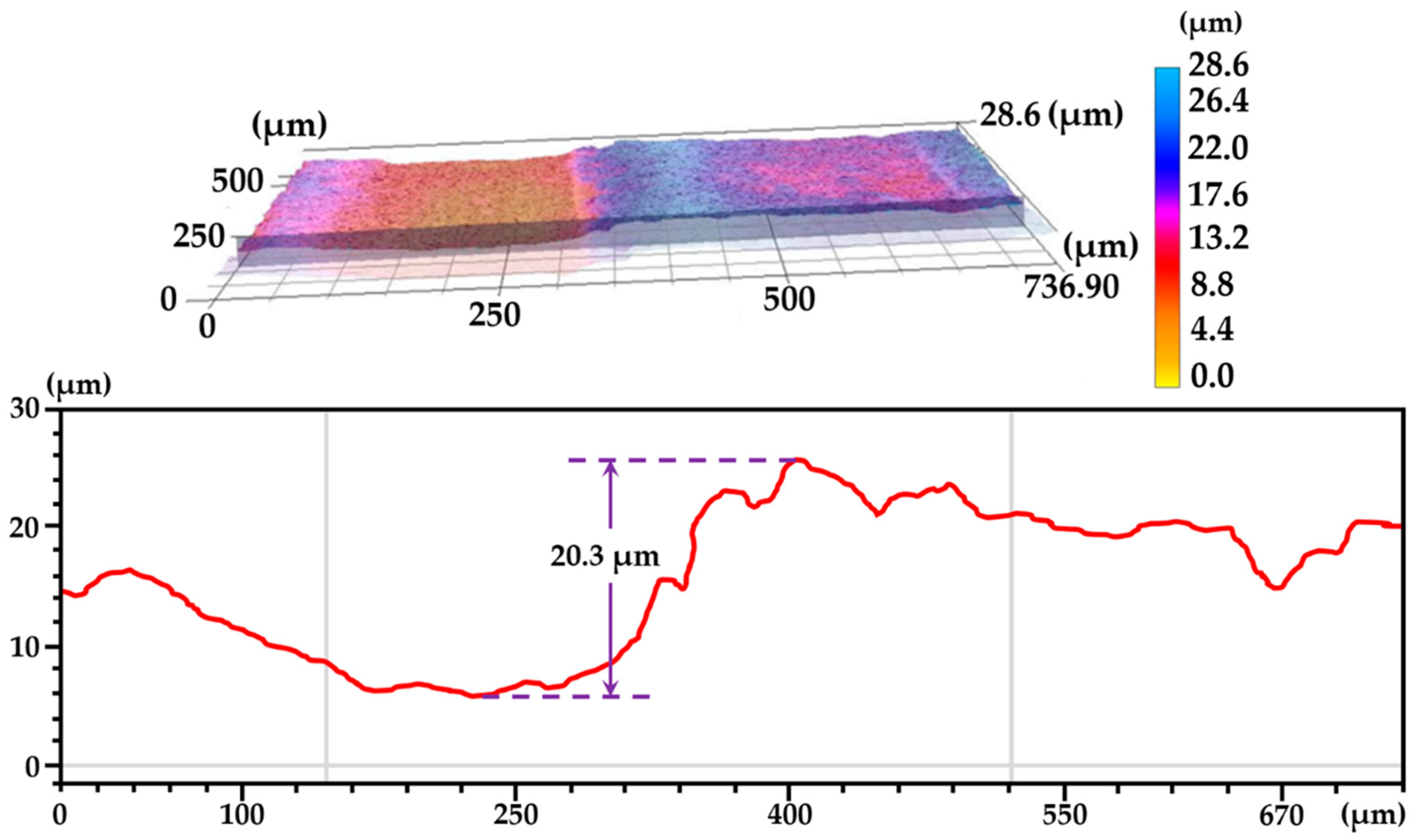
After printing the horn antenna, it was important to smooth the surface thoroughly before plating. Although high print quality was applied, the resulting surface was not perfectly smooth. Figure 11 and Figure 12 show the unevenness of the printed horn antenna surface using the Keyence VHX-7000 microscope. For this reason, the horn antenna was printed from two parts. This made the surface smoothing process easier (also that inside the horn antenna).
Furthermore, galvanic plating was applied and the two plated parts were glued together after plating. To smooth the surface, a grinding with different types of sandpaper grains was applied (see Figure 13).
3.4. Preparing Printed Antenna for Galvanic Plating
After achieving the necessary smoothness of the horn antenna surface, the surface was further cleaned for dirt and grease. Galvanic plating is a method where metal layers are gradually applied until the surface is perfectly plated with a complete layer. A 24-carat piece of gold (99.99% Au) was used for the plating of our 3D printed horn antenna. Gold plating ensures functional surface properties featuring good electrical conductivity, chemical stability, corrosion resistance and long service life. The market currently offers all-metal horn antennas with gold-plated surfaces. For our gold plating, a LISS, a.s. company was used, providing a number of high-tech manufacturing technologies for the metallization of non-conductive materials [26].
To reduce the final price of gold plating, the first layer, i.e., the bottom layer, was plated with silver. Silver was applied to the antenna surface (made of ABS filament) using a “spraying” technique, preparing the surface for the final gold plating. This initial silver plating was the most important process in the whole plating process, significantly increasing the success of the final gold application. Silver was applied in thin layers in the order of units of μm until a layer of 25–30 μm was reached (this is an economical option for gold plating). In addition, silver helps to strengthen the mechanical properties of the horn antenna’s plastic parts, especially toughness. The final upper layer was a “flash” layer of 24-carat gold (purity 999/1000) with a thickness of 0.3 μm.
The galvanic application was carried out manually, without automation. Manual application ensured the necessary thickness and quality of the metal layers. Some initial attempts at the gold plating were unsuccessful, and thus it was necessary to determine the minimum size of the gold layer that would assure the final gold surface had no defects. Figure 14 left shows the horn antenna flange with a gold layer of 0.2 μm. This layer proved insufficient as several gaps appeared in the gold layer. Figure 14 right shows a gold layer of 0.3 μm that shows no gaps in the gold layer, and thus, the correct parameters.
To measure the thickness of the applied metal layers, the Fischerscope X-RAY XDAL 237 universal X-ray-fluorescence spectrometer was used. This method is ideal for measuring layer thickness as it is a non-destructive method.
4. Testing the Standardised and Printed Horn Antenna
For the reason of uniform deposition of the metallic layers, the individual components of the printed antenna were manufactured separately. The individual components of the printed horn antenna have to be glued together using plastic glue. Figure 16 shows an assembled horn antenna with a gold-plated surface.
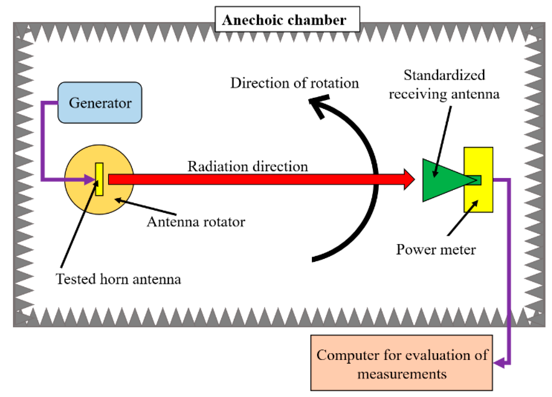
In order to compare the radiation patterns of the standardised horn antenna and the printed horn antenna, it is necessary to perform the measurements in an anechoic chamber to eliminate the negative influence of the surrounding environment on the experiment.
Tests of the printed antenna were performed in an anechoic (non-reflective) chamber.
Figure 17 shows the test setup in the anechoic chamber and Figure 18 shows the measured horn antenna position on the antenna rotator in the anechoic chamber. All tests were carried out at a frequency of 9.5 GHz.
4.1. Testing the Standardised Horn Antenna
Figure 19 shows the measured radiation of the standardised horn antenna in the non-reflective chamber. The red line represents the radiation flow in the E plane and the green line in the H plane.
Measurements at 9.5 GHz showed that the standardised horn antenna has an aperture angle of 40 degrees in the E plane and an aperture angle of 20 degrees in the H plane. Using a Rohde & Schwarz analyser, the standing wave ratio was measured in the frequency range from 8 to 11.3 GHz.
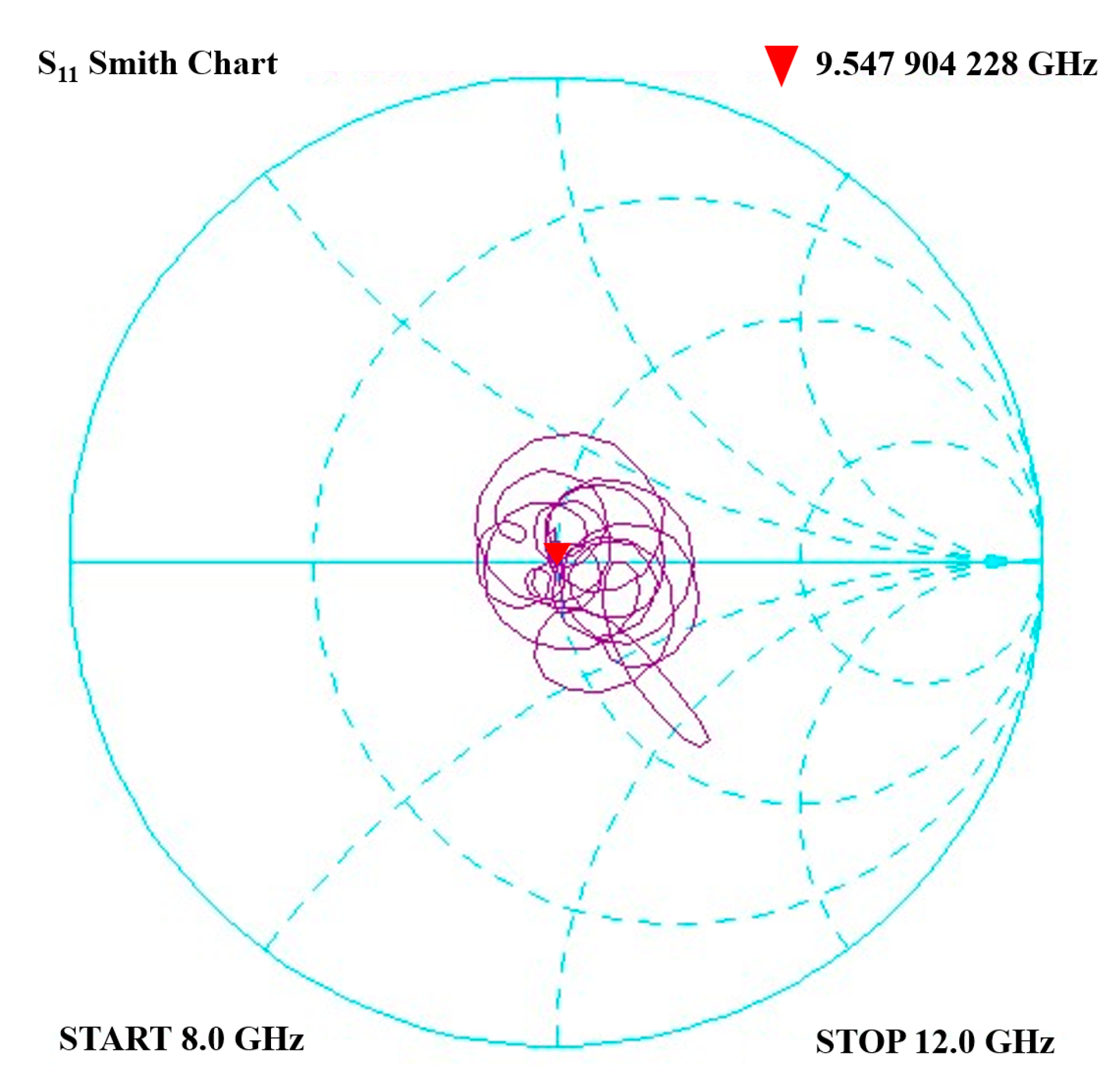
Figure 20 shows the measured Stand Wave Ratio (SWR), and Figure 21 shows the measured Smith diagram for the standardised horn antenna.
The results of the SWR measurements and the plot of the reflection coefficient s11 on the Smith chart show that the normalized horn antenna has optimal characteristics at 9.54 GHz. The obtained results should be compared with those of the printed horn antenna.
4.2. Testing the 3D Printed Horn Antenna
Figure 22 shows the measured radiation of the 3D printed horn antenna in the non-reflective chamber. The red line represents the radiation flow in the E plane and the green line that in the H plane.
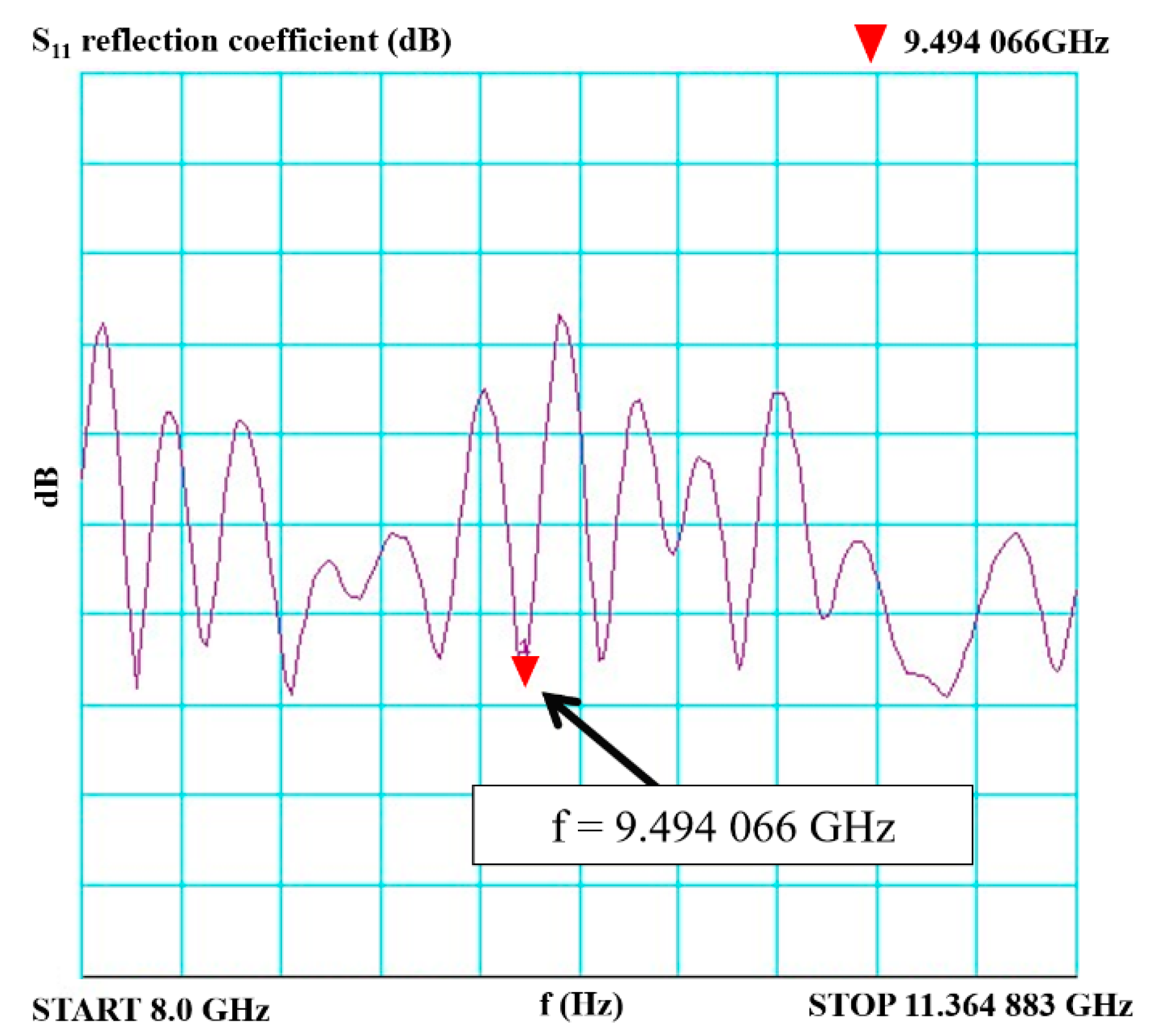
Measurements at 9.5 GHz showed that the printed horn antenna has an aperture angle of 40 degrees in the E plane and an aperture angle of 30 degrees in the H plane. Figure 23 shows the measured Stand Wave Ratio (SWR), and Figure 24 shows the measured Smith diagram for the 3D printed horn antenna.
The results of SWR measurements and the plot of the reflection coefficient s11 on the Smith chart show that the printed horn antenna has optimal characteristics at 9.494 GHz. Comparing the results obtained for the standardised horn antenna and the printed horn antenna results, it is clear that the printed horn antenna has very similar results to the standardised horn antenna. This means that the manufacturing process of the printed horn antenna is correct. The printed horn antenna achieves very similar characteristics to the standardised horn antenna. The results show that the printed horn antenna can be used in practical applications as an equivalent to the standardised horn antenna.
5. Discussion
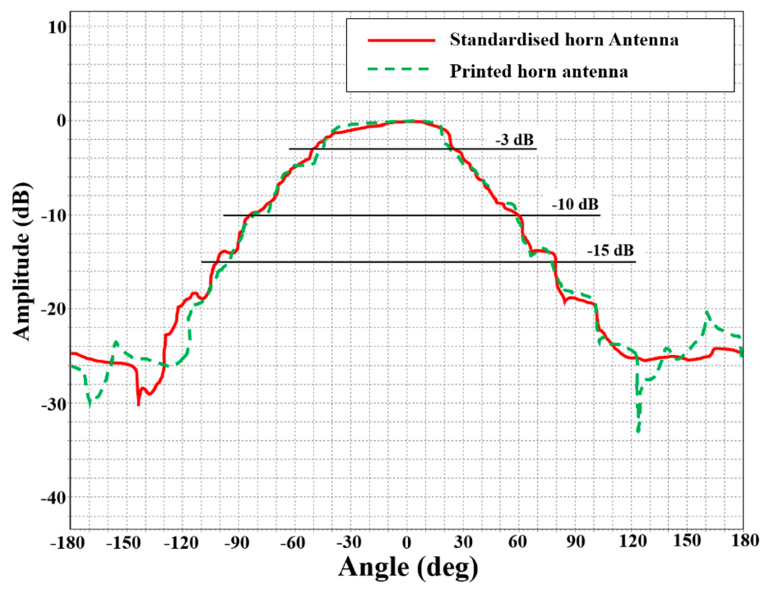
The presented test results clearly show that the 3D printed horn antenna is fully functional. Figure 25 shows a comparison of the standardised horn antenna characteristics with the 3D printed horn antenna characteristics in the E plane. The red line shows the radiation characteristics of the standardised horn antenna and the green line those of the 3D printed horn antenna.
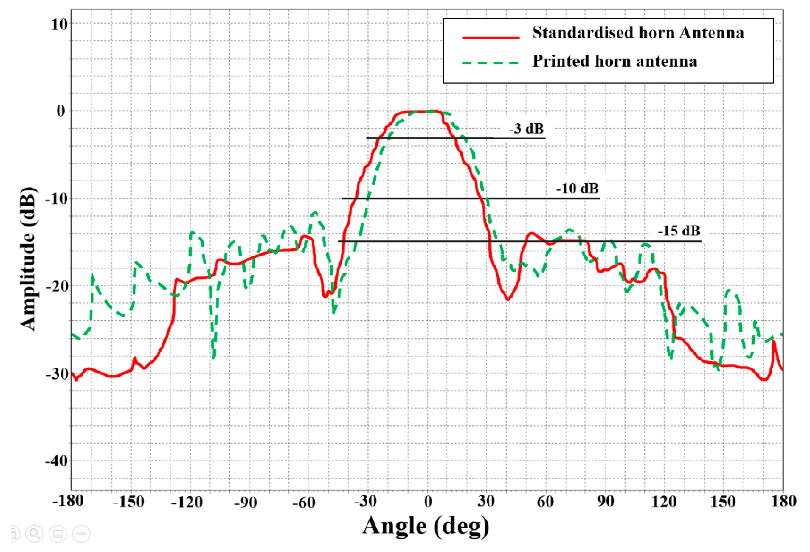
Figure 26 shows a comparison of the radiation patterns of the standardised horn antenna with the 3D printed horn antenna in the H plane. The red line shows the radiation characteristics of the standardised horn antenna and the green line those of the 3D printed horn antenna.
After the completion of the 3D printed horn antenna, both the standardised and the printed antennas were weighed. The weight of the standard (all-metal) horn antenna was 139 g. The weight of the 3D printed gold-plated (metallic spraying method) horn antenna was 13 g, which is approximately 10% of the standardised all-metal horn antenna weight. This weight reduction is beneficial, for example, in applications where horn antennas are placed onboard aircraft, serving as onboard radio locator antennas.
Experiments have shown that the described method of manufacturing a horn antenna, based on 3D printing and with silver–gold galvanic plating layers, is a suitable method for the production of antennas where extremely low weight is required. By following the technological procedure during the 3D printing of the antenna, depending on the choice of filament material, and by following the technological procedure during the process of electroplating the metallic layers on the printed antenna, it is possible to obtain a horn antenna with equivalent properties to a standardised horn antenna.
6. Conclusions
The article described how to use 3D printing for the manufacturing of a horn antenna. The main goal was to verify the proposed manufacturing technological procedure and to compare the printed antenna to a standardised horn antenna. The results show that the 3D printed and plated horn antenna has the same parameters as a standardised horn antenna. The presented antenna manufacturing procedure is suitable not only for the presented horn antenna, but also for all different types of antennas. The only limitation is the size of the 3D printer print area. The use of 3D printing with galvanic plating offers the manufacturing of exact antennas with specific radiation parameters, and thus is very suitable for experimental testing of various antenna prototypes or antenna systems. Another great advantage is the low weight of the manufactured antenna. This low weight is beneficial for special applications where weight reduction in the whole system is crucial.
The production of equivalents of standardised antennas using 3D printing with electroplating is also a possible route for the design and realization of other types of antennas, e.g., slot antennas and slot antenna arrays used in the aerospace industry. Similarly, 3D printed antennas can also be used for small satellites and space exploration equipment.
Author Contributions
Conceptualization, J.O. and M.R.; methodology, M.P.; validation, E.Š., M.P. and M.R.; formal analysis, M.R.; investigation, E.Š.; resources, E.Š.; data curation, J.O.; writing—original draft preparation, M.P.; writing—review and editing, J.O.; visualization, E.Š.; supervision, M.R.; project administration, J.O.; funding acquisition, J.O. All authors have read and agreed to the published version of the manuscript.
Funding
This research received no external funding.
Acknowledgments
The work presented in this article was supported by specific research of the University of Defence entitled “Modern Antenna Systems and Methods of their Management”, and by the Czech Republic Ministry of Defence—the University of Defence development program “AIROPS”. Thanks also to LISS, a company for using their galvanic plating technology for the printed horn antenna.
Conflicts of Interest
The authors declare no conflict of interest.
References
- Yerbolat, G.; Shynggys, A.; Ali, M.H. Mechanical Property Prediction Method Based on Multi-material 3D Printer. In Proceedings of the 2018 Joint 7th International Conference on Informatics, Electronics & Vision (ICIEV) and 2018 2nd International Conference on Imaging, Vision & Pattern Recognition (icIVPR), Kitakyushu, Japan, 25–29 June 2018; pp. 498–502. [Google Scholar] [CrossRef]
- Alvarez, D.; Vásquez, C. Improvements to control system of a multi-extruder 3D printer using a controller duet card. In Proceedings of the Congreso Internacional de Innovacin y Tendencias en Ingeniera (CONIITI), Bogota, Colombia, 4–6 October 2017. [Google Scholar] [CrossRef]
- Hoque, M.M.; Jony, M.M.H.; Hasan, M.M.; Kabir, M.H. Design and Implementation of an FDM Based 3D Printer. In Proceedings of the 2019 International Conference on Computer, Communication, Chemical, Materials and Electronic Engineering (IC4ME2), Rajshahi, Bangladesh, 11–12 July 2019; pp. 1–5. [Google Scholar] [CrossRef]
- Available online: https://www.prusa3d.com/prusaslicer/#_ga=2.201229934.1128987098.1626340328-1785738773.1626340328 (accessed on 15 March 2022).
- Available online: https://www.autodesk.com (accessed on 11 February 2022).
- Kowalski, W.P.; Roman, M. Autodesk inventor professional as common platform CAD for designer from mechanic and electromechanic profession. In Proceedings of the International Conference on Modern Problems of Radio Engineering, Telecommunications and Computer Science, Lviv-Slavsko, Ukraine, 28 February 2004. [Google Scholar]
- Available online: https://www.onshape.com (accessed on 10 February 2022).
- Balanis, A.C. Modern Antenna Handbook; John Wiley and Sons, Publishers, Inc.: New York, NY, USA, 2008; ISBN 9780470036341. [Google Scholar]
- Balanis, A.C. Antenna Theory: Analysis and Design, 3rd ed.; John Wiley: Hoboken, NJ, USA, 2005; ISBN 978-0-471-66782-7. [Google Scholar]
- Stutzman, W.L.; Thiele, G.A. Antenna Theory and Design; John Wiley: Hoboken, NJ, USA, 2012; ISBN 0470576642. [Google Scholar]
- Werner, H.D. Broadband Metamaterials in Electromagnetics, 1st ed.; Jenny Stanford Publishing: Dubai, United Arab Emirates, 2017; ISBN 9789814745680. [Google Scholar]
- Rudge, A.W.; Milne, K.; Olver, A.D.; Knight, P. Handbook of Antenna Design; IET: London, UK, 1982; Volume 2, ISBN 9780906048870. [Google Scholar]
- Gong, L.; Fu, Y.; Chan, K.Y.; Nanzer, J.A. An SIW Horn Antenna Fed by a Coupled Mode Emulating Pyramidal Horn Antennas. IEEE Trans. Antennas Propag. 2019, 68, 99. [Google Scholar] [CrossRef]
- Marowsky, G. Planar Waveguides and Other Confined Geometries; Springer: New York, NY, USA, 2014; ISBN 1493911783. [Google Scholar]
- Westerveld, W.J.; Urbach, H.J. Silicon Photonics: Electromagnetic Theory; IOP Publishing Ltd.: Bristol, UK, 2017; ISBN 978-0-7503-1387-2. [Google Scholar]
- Mahmoud, S.F. Electromagnetic Waveguides: Theory and Applications; Publishing Ltd. Institute of Electrical Engineers: Piscataway, NJ, USA, 1991; ISBN 0863412327. [Google Scholar]
- Ismail, W.; Murad, S.A.Z.; Jiat, T.J.; Mandeep, J.S. Integrated power dividing antenna receivers. Microw. J. 2009, 52, 88–106. [Google Scholar]
- Milligan, T.A. Modern Antenna Design, 2nd ed.; John Wiley & Sons, Publishers, Inc.: Hoboken, NJ, USA, 2005; ISBN 9780471720614. [Google Scholar]
- Huang, S.; Chan, K.Y.; Wang, Y.; Ramer, R. High Gain SIW H-Plane Horn Antenna with 3D Printed Parasitic E-Plane Horn. Electronics 2021, 10, 2391. [Google Scholar] [CrossRef]
- Russo, A.C.; Andreassi, G.; di Girolamo, A.; Pappada, S.; Buccoliero, G.; Barile, G.; Vegliò, F.; Sotornelli, V. FDM 3D Printing of high performance composite materials. In Proceedings of the Workshop on Metrology for Industry 4.0 and IoT, Naples, Italy, 4–6 June 2019. [Google Scholar] [CrossRef]
- Hasan, M.; Hoque, M.; Jony, M.H.; Kabir, M.H. Design of the ABS polymer based multimode planar large core 1 × 2 splitter fabricated by 3D printing technology. In Proceedings of the International Conference on Computer, Communication, Chemical, Material and Electronic Engineering (IC4ME2), Rajshahi, Bangladesh, 11–12 July 2019. [Google Scholar] [CrossRef]
- Kim, S.; Chung, K.; Yu, H.; Yang, S.O. G-code conversion from 3D model data for 3D printers on Hadoop systems. In Proceedings of the 2017 4th International Conference on Computer Applications and Information Processing Technology (CAIPT), Kuta Bali, Indonesia, 8–10 August 2017; pp. 1–4. [Google Scholar] [CrossRef]
- Zheng, X.H.; Ding, S.T.; Wu, Y.M.; Xiao, H.; Qi, J.C.; Niu, J.W. Dimension extraction from three dimensional (3D) hand data without prior manual landmarking. In Proceedings of the International Conference on Industrial Engineering and Engineering Management (IE&EM), Changchun, China, 3–5 September 2011. [Google Scholar] [CrossRef]
- 2075:2013-SMPTE; Standard-Mapping EBU TECH 3264 (STL) into the MXF Generic Stream Container. SMPTEST: White Plains, NY, USA, 2013; ISBN 978-1-61482-754-2.
- Available online: https://www.prusa3d.com/prusaslicer/#_ga=2.243197762.1128987098.1626340328-1785738773.1626340328 (accessed on 15 April 2022).
- Available online: https://liss.cz/electroplating/?lang=en (accessed on 12 April 2022).
Figure 1.
Horn antenna (a) in Autodesk Inventor program; (b) in Onshape program.

Figure 2.
Standardised horn antenna.

Figure 3.
E-sector horn antenna.

Figure 4.
Horn antenna dimensions.

Figure 5.
Waveguide model WR90 (R100) with dimensions.

Figure 6.
Standardised horn antenna designed in Matlab Antenna Toolbox.

Figure 7.
Three-dimensional radiation characteristics of a standardised horn antenna.

Figure 8.
Simulation of the standardised horn antenna for a frequency of 9.5 GHz, (a) horizontally; (b) vertically.
Figure 8.
Simulation of the standardised horn antenna for a frequency of 9.5 GHz, (a) horizontally; (b) vertically.

Figure 9.
Horn antenna designed in PrusaSlicer [5].
Figure 9.
Horn antenna designed in PrusaSlicer [5].

Figure 10.
Settings of the main parameters for 3D printing [5].
Figure 10.
Settings of the main parameters for 3D printing [5].

Figure 11.
Print quality 0.1 mm, magnified 20× and 400×.

Figure 12.
Unevenness at 0.1 mm print quality using Keyence VHX microscope (all distance values in the figure are in units of µm).
Figure 12.
Unevenness at 0.1 mm print quality using Keyence VHX microscope (all distance values in the figure are in units of µm).

Figure 13.
Comparison of horn antenna surface, 10×-magnified left before smoothing the surface; right after smoothing the surface.
Figure 13.
Comparison of horn antenna surface, 10×-magnified left before smoothing the surface; right after smoothing the surface.

Figure 14.
Horn antenna flange with (left) wrong thickness of gold layer; (right) proper thickness of gold layer.
Figure 14.
Horn antenna flange with (left) wrong thickness of gold layer; (right) proper thickness of gold layer.

Figure 15.
Horn antenna set with gold-plated surface.

Figure 16.
Assembled horn antenna with a gold-plated surface.

Figure 17.
Test setup in the anechoic chamber.

Figure 18.
Horn antenna placed on the antenna rotator in anechoic chamber.

Figure 19.
Measured radiation characteristics of the standardised horn antenna.

Figure 20.
Parameter SWR of the standardised horn antenna.

Figure 21.
Smith diagram parameter S11 of the standardised horn antenna.

Figure 22.
Radiation of the 3D printed horn antenna in the non-reflective chamber.

Figure 23.
Parameter SWR of the printed horn antenna.

Figure 24.
Smith diagram parameter S11 of the printed horn antenna.

Figure 25.
Comparison of radiation characteristics of the standardised (red) and 3D printed horn antennas in the E plane (green).
Figure 25.
Comparison of radiation characteristics of the standardised (red) and 3D printed horn antennas in the E plane (green).

Figure 26.
Comparison of radiation characteristics of the standardised (red) and 3D printed (green) horn antennas in the H plane.
Figure 26.
Comparison of radiation characteristics of the standardised (red) and 3D printed (green) horn antennas in the H plane.


Table 1.
Dimensions of the analysed horn antenna with Adapter.
| Designation | Dimension [mm] | Title |
|---|---|---|
| l1 | 52.00 | Estuary length |
| h1 | 45.00 | Estuary height |
| w1 | 23.00 | Estuary width |
| l2 | 50.00 | Waveguide length |
| h2 | 10.16 | Waveguide height |
| w2 | 22.86 | Waveguide width |
| h3 | 8.00 | Current probe height |
| w3 | 5.00 | Current probe width |
Table 2.
Comparison of different types of materials (filaments).
| Filament | PLA | PET/PET-G | ABS |
|---|---|---|---|
| Nozzle temperature during printing | 180–230 °C | 220–260 °C | 210–250 °C |
| Melting point | 150–160 °C | - | 130–140 °C |
| Deformation | 60 °C | 100 °C | 70 °C |
Table 3.
Thickness measurements of the galvanically applied layers.
| Measurement | Layer Thickness Au [μm] | Layer Thickness Ag [μm] |
|---|---|---|
| 1 | 0.323 | 28.4 |
| 2 | 0.321 | 30.0 |
| 3 | 0.355 | 30.6 |
Publisher’s Note: MDPI stays neutral with regard to jurisdictional claims in published maps and institutional affiliations. |
© 2022 by the authors. Licensee MDPI, Basel, Switzerland. This article is an open access article distributed under the terms and conditions of the Creative Commons Attribution (CC BY) license (https://creativecommons.org/licenses/by/4.0/).
Share and Cite
MDPI and ACS Style
Olivová, J.; Popela, M.; Richterová, M.; Štefl, E. Use of 3D Printing for Horn Antenna Manufacturing. Electronics 2022, 11, 1539. https://doi.org/10.3390/electronics11101539
AMA Style
Olivová J, Popela M, Richterová M, Štefl E. Use of 3D Printing for Horn Antenna Manufacturing. Electronics. 2022; 11(10):1539. https://doi.org/10.3390/electronics11101539
Chicago/Turabian StyleOlivová, Jana, Miroslav Popela, Marie Richterová, and Eduard Štefl. 2022. "Use of 3D Printing for Horn Antenna Manufacturing" Electronics 11, no. 10: 1539. https://doi.org/10.3390/electronics11101539
Note that from the first issue of 2016, this journal uses article numbers instead of page numbers. See further details here.