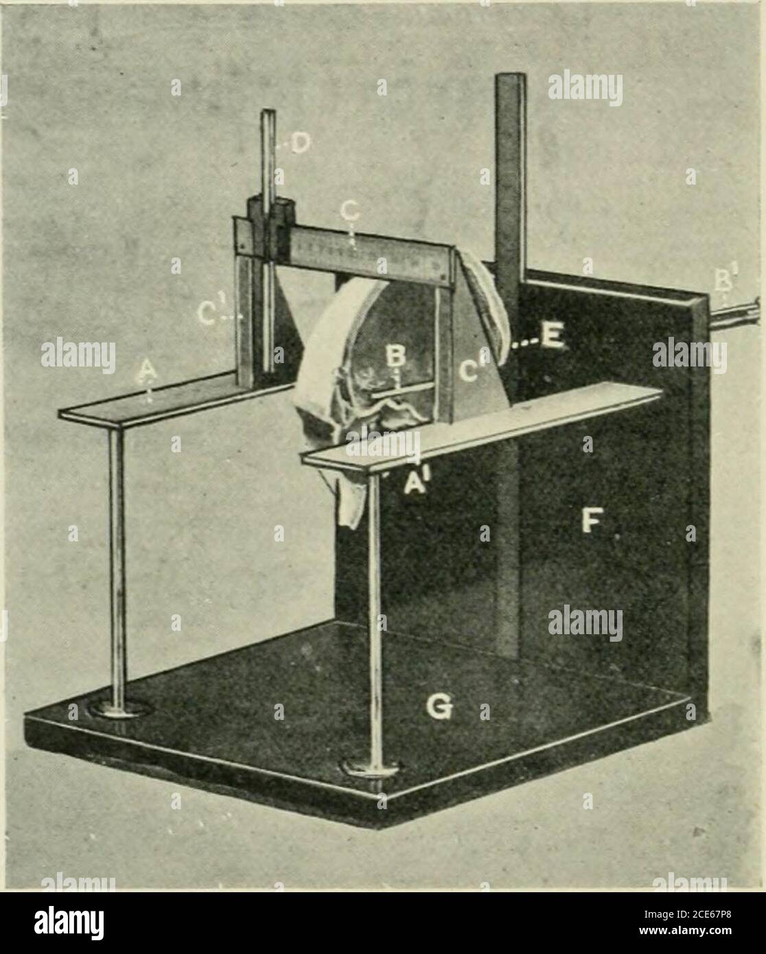
. Journal of anatomy . be pushed forwards in front of the vertical plate for an. Fig. 1.—Craniometer with skull (20S mm. long). The skull is bisected in thespecimen shown in order to show the position of the orienting rod B B. A, A, lateral plates, marked with millimetre scale, zero being at tlieir commencement at the verticalplate (F); B B, orienting rod; it works along a vernier placed behind the vertical plate (K);C, the bridge ; C C, uprights of bridge ; D, sliding indicator ou bridge ; E, zero-point, whereorienting rod perforates the vertical plate ; F, vertical plate; G, foot-plate. exte
Image details
Contributor:
Reading Room 2020 / Alamy Stock PhotoImage ID:
2CE67P8File size:
7.2 MB (246.7 KB Compressed download)Releases:
Model - no | Property - noDo I need a release?Dimensions:
1465 x 1706 px | 24.8 x 28.9 cm | 9.8 x 11.4 inches | 150dpiMore information:
This image is a public domain image, which means either that copyright has expired in the image or the copyright holder has waived their copyright. Alamy charges you a fee for access to the high resolution copy of the image.
This image could have imperfections as it’s either historical or reportage.
. Journal of anatomy . be pushed forwards in front of the vertical plate for an. Fig. 1.—Craniometer with skull (20S mm. long). The skull is bisected in thespecimen shown in order to show the position of the orienting rod B B. A, A, lateral plates, marked with millimetre scale, zero being at tlieir commencement at the verticalplate (F); B B, orienting rod; it works along a vernier placed behind the vertical plate (K);C, the bridge ; C C, uprights of bridge ; D, sliding indicator ou bridge ; E, zero-point, whereorienting rod perforates the vertical plate ; F, vertical plate; G, foot-plate. extent of 200 mm. By this rod it is easy to determine the position ofthe following points in the antero-posterior plane: (1) the dorsum sellse ;(2) the olivary eminence and optic groove ; (3) the position of the right andleft frontal poles of the brain. When the interior of the skull is artificiallyilluminated, the anterior end of the cribriform plate can also be determined.When the human skull is inverted (see fig. 2) and the rod pushed within itto an extent of 130-14-0 mm., t